
Fire suppression system installation: a step-by-step guide
A fire suppression system is only as good as the way it is installed. The best-specified clean-agent or sprinkler design will still fail its purpose if the pipework is unsupported, the nozzles point at the wrong hazard, or the detection never talks to the control panel. This guide walks through a professional fire suppression system installation from first survey to final handover. You will see what a competent contractor should be doing on your site, and where the common mistakes hide.
1. Site survey and design basis
Every serious fire suppression system installation begins on site, not on a drawing board. The survey establishes the design basis: what is being protected, from what kind of fire, and under what constraints. An engineer measures the room or hazard volume, records ceiling heights, notes obstructions such as beams, ducts and cable trays, and checks for ventilation openings that would let an extinguishing agent escape. For a total-flooding gas system, this is where room integrity is first assessed; for a sprinkler or foam system, it is where hazard classification and water supply are pinned down.
The survey also captures the practical realities that decide how the job runs: access routes for cylinders and pipe, the location of the future control panel, cable pathways, and any live services that constrain the route. A thorough survey prevents the single most expensive class of problem, namely discovering on assembly day that the design cannot physically be built where it was drawn.
The design basis is the reference every later decision is checked against. Suppose the protected volume, hazard class or occupancy changes after installation: a room repurposed, a mezzanine added, a cooking line extended. The system must then be reassessed. A documented basis makes that judgement possible instead of a guess.
2. Agent and system selection
With the hazard understood, the right suppression concept is chosen. The agent must match what is burning and what must survive: water or sprinklers for ordinary combustibles, foam for flammable liquids, wet chemical for cooking-oil fires, and clean agents or inert gas where water would destroy the very assets being protected. Selection is not a catalogue exercise. It balances effectiveness, occupancy safety, environmental impact, downtime after a discharge and lifetime cost. Our guide to choosing a fire suppression system works through those trade-offs in detail, and the complete fire suppression systems guide explains each agent family.
Getting selection right before installation is critical because the agent drives everything downstream: pipe sizes, cylinder count, nozzle type, discharge time and the interlocks the system needs. Changing the agent after pipework is fabricated is not a tweak. It is a redesign.
3. Hydraulic and pipe design
Before a single length of pipe is cut, the system is calculated. For water-based systems this is a hydraulic calculation under EN 12845, proving that every remote sprinkler receives its required flow and pressure at the design density. For gas and clean-agent systems the flow calculation follows EN 15004 / ISO 14520 and the manufacturer's approved software, verifying that the agent reaches every nozzle within the required discharge time and at the correct concentration, with pipe volume, fittings and elevation all accounted for. The output is a bill of materials and a pipe schedule with exact diameters, lengths and fitting counts.
This stage is where an experienced installer earns their fee. Undersized pipe starves the far nozzles. Oversized pipe wastes agent and money. Too many fittings on a gas system can push discharge time past the ten-second limit that most clean agents work to. The calculation is not optional paperwork. It is the proof that the physical build will actually perform.
| Stage | Purpose | Key verification |
|---|---|---|
| Site survey | Establish the design basis | Volume, hazard class, room integrity |
| Hydraulic / flow design | Prove performance on paper | Calculation sign-off |
| Pipework & mounting | Build the distribution network | Bracket spacing, alignment |
| Nozzle placement | Deliver agent to the hazard | Coverage, orientation, clearances |
| Wiring & integration | Connect detection and control | Loop continuity, interlocks |
| Pressure / leak test | Confirm integrity | Hold test at rated pressure |
| Commissioning | Prove the whole system works | Functional test, certificate |
| Handover | Transfer records and duties | As-builts, O&M manual |
4. Pipework fabrication and mounting
Now the system takes physical shape. Pipe is cut, threaded or grooved, and assembled to the pipe schedule. Clean fabrication matters more than it looks: burrs and swarf left inside the pipe can block a nozzle at the worst possible moment, so bore cleanliness is checked as pipe is made up. Runs are set out to follow the design route, kept clear of moving plant and thermal sources, and pitched where a system needs to drain.
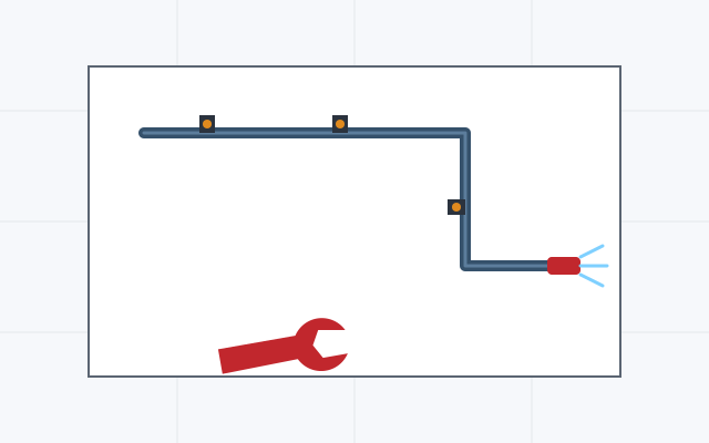
Mounting is governed by bracket and support standards. Supports carry the static weight of pipe and agent, and they also carry the dynamic thrust of a discharge. A gas system releasing in seconds imposes real reaction forces on the network. Bracket spacing follows the pipe diameter and material, typically every two to three metres on smaller bore and closer on larger, with additional restraint at changes of direction, at nozzles and near cylinders. Under-bracketing is one of the most common and most dangerous shortcuts in the trade.
Well-installed pipework is straight, evenly supported, and labelled. Consistent bracket spacing, neat fittings made up to the correct engagement, and clear identification of pipes and valves are visible signs that the hidden work was done properly too: bore cleanliness, calculation and correct torque.
5. Nozzle placement and coverage
Nozzles are the business end of the system, and their placement is dictated by the design, never by convenience. Each nozzle type has an approved coverage area, throw and mounting orientation. For total-flooding gas systems, nozzles must distribute agent evenly through the volume within the discharge time. For kitchen and sprinkler systems, each nozzle is aimed at a defined hazard, whether a specific appliance, a duct or a floor area, with the manufacturer's required clearances from walls, obstructions and heat sources.
Installers verify that no obstruction blocks a nozzle's pattern, that heights and angles match the approved layout, and that the correct nozzle model and orifice size are fitted at every point. A single wrong or blocked nozzle can leave part of a protected space effectively uncovered.
6. Detection, wiring and panel integration
A suppression system that cannot detect a fire, or cannot be told to act, is only half a system. This stage installs the detection, using smoke, heat, flame or aspirating detectors as the design requires, and wires it back to the control panel on monitored loops so a fault or a break is itself flagged. Detectors and the releasing panel carry EN 54 approval, the standard that covers fire-detection components and their integration. Releasing devices, manual call points, abort switches and warning signals are wired in, along with the interlocks that shut down ventilation, close dampers or trip power to protected equipment on activation.
Integration is where fire protection meets the rest of the building. The panel may need to signal a building management system, a monitoring centre or a wider fire alarm. Every input and output is documented so that, later, anyone can trace what triggers what. For sensitive spaces this detection strategy is decisive. Our server room fire protection guide shows how very early detection changes the whole response.
7. Pressure and leak testing
Before anything is declared finished, the installed network is tested for integrity. Pipework is pressure- or leak-tested to the standard for the system type and held under pressure for a defined period. Cylinder connections, valves and fittings are checked. On clean-agent systems the pipe network is proven against leakage that would let agent bleed away and undershoot concentration. Any pressure test is planned as a controlled activity, with the system isolated and the area managed, because stored energy is involved.
Leak and pressure testing is the last chance to catch a fabrication fault before the system is entrusted with lives and assets. A network that will not hold a test is not ready to be commissioned. Full stop.
A pipe that passes a momentary pressure spike but slowly loses pressure over the hold period has a leak that will matter on the day of a fire. Rushing or shortening the hold test to save time is a false economy that can quietly disable the entire system.
8. Commissioning and functional discharge tests
Commissioning is the formal proof that the finished system works as designed. Detection is tested device by device, the alarm and warning sequence is verified, and interlocks are confirmed to fire in the right order. Releasing circuits are proven safely, with cylinders isolated where appropriate. Where the design calls for it, a functional discharge or a controlled equivalent test demonstrates that the agent actually reaches the space. On gas systems, a room integrity (door-fan) test confirms the enclosure holds the concentration for the required hold time.
This is a planned, coordinated event, often the one stage that needs a controlled shutdown of the protected area. It is witnessed and recorded, and it produces the commissioning certificate that an insurer or authority relies on. A system that has not been commissioned is, from a compliance standpoint, an unverified assembly of parts.
- Detection verified. Every detector tested and its zone confirmed at the panel.
- Alarms and signals. Audible and visual warnings proven throughout the protected area.
- Interlocks. Ventilation shutdown, damper closure and power trips fire in the correct sequence.
- Releasing circuits. Proven safely, with cylinders isolated during electrical testing.
- Discharge / integrity. Functional test or room integrity check passed and recorded.
- Certificate issued. Commissioning documented and signed off.
9. Documentation and handover
The last stage of a fire suppression system installation is the transfer of knowledge and responsibility. A complete handover pack includes as-built drawings that reflect what was actually installed, the hydraulic or flow calculation, component and cylinder data sheets, pressure-test and commissioning certificates, an operating and maintenance manual, and a recommended service schedule. The people who will operate the building are briefed on how the system behaves, what the panel indicates, and what to do on activation.
Good documentation is not bureaucracy. It is the baseline for the entire service life of the system. Every future inspection is measured against it, and the first thing a maintenance technician asks for is the handover pack. If you want to see what happens next, our fire suppression maintenance and inspection guide explains the servicing regime that keeps the installed system reliable.
10. Common installation mistakes to avoid
Most installation failures are not exotic. They are a handful of avoidable errors that recur across sites. Knowing them helps you judge whether your installation was done properly.
- Skipping the survey. Building to an office drawing without validating volumes, obstructions and room integrity on site.
- Under-supported pipework. Too few brackets, missing restraint at nozzles and bends, ignoring discharge thrust.
- Dirty pipe. Swarf and burrs left inside that later block a nozzle.
- Wrong or misaimed nozzles. Convenient placement that ignores approved coverage, clearances and orientation.
- Detection not integrated. Suppression fitted but interlocks, dampers or shutdowns never wired or tested.
- No hold test. Leaks accepted because the pressure test was cut short.
- Uncommissioned handover. A system left "installed" but never formally proven or certificated.
- Missing documentation. No as-builts or calculations, leaving every future service and change a guess.
When survey, design, supply, installation and commissioning sit with a single competent partner, responsibility never falls between trades. VAALMAX supports this chain from consulting through installation to maintenance. See our installation service or request a consultation for your building or process.
Frequently asked questions
How long does a fire suppression system installation take?
A single-room clean-agent or kitchen system is often installed in a few days. A zoned building or industrial project can take several weeks. The physical assembly is rarely the bottleneck. Survey, design approval, material lead times and coordinating a controlled commissioning discharge usually drive the schedule.
Can it be done while the building stays in use?
Frequently, yes. Pipework fabrication, bracket mounting and wiring can be staged around occupancy, and detection can be added zone by zone. The one stage that needs a controlled shutdown is final commissioning and any functional discharge test. That is planned with the site to minimise disruption.
Who is allowed to install a fire suppression system?
Installation should be carried out by a competent, trained contractor working to the manufacturer's approved design and to the relevant standard, EN 12845 for sprinklers or EN 15004 / ISO 14520 for gaseous systems. Gas and clean-agent systems in particular must be installed by technicians certified for that specific system, because nozzle selection, pipe volumes and cylinder charging are all design-critical.
What is commissioning, and why does it matter?
Commissioning is the formal process of proving the finished system works as designed: detection, alarms, interlocks, releasing devices and, where applicable, actual agent discharge or a controlled functional test. Without documented commissioning, a system is unverified and may not be accepted by an insurer or authority.
Do I get documentation after the installation?
You should. A proper handover pack includes as-built drawings, the hydraulic or design calculation, component data sheets, test and commissioning certificates, an operating and maintenance manual, and the recommended service schedule. Keep it safe. It is the baseline for every future inspection.
A dependable fire suppression system installation is a disciplined sequence: survey the hazard and fix the design basis, select the right agent, calculate the pipework to EN 12845 or EN 15004, then fabricate, mount, place nozzles, wire and integrate detection, and finally pressure-test, commission and hand over with full documentation. Avoid the recurring mistakes of skipped surveys, weak supports and uncommissioned handovers, and the system will do its job when it matters. For related reading, see our systems overview, maintenance guide and server-room protection guide.
Planning an installation?
Tell us about your building or process. We will survey the hazard and recommend a system that can be installed cleanly and commissioned properly.